
Spine
April 11, 2024
Spine
Learning Objective: Examine the process for performing spinal images.
The bones of the spine are divided into the cervical spine, thoracic spine, and lumbar spine. This area also includes the sacrum, coccyx, and sacroiliac joints. The examinations of the cervical spine are most commonly performed at the wall Bucky with the patient upright, whereas those for the thoracic spine and lumbar spine are typically performed in the table Bucky with the patient recumbent.
Landmarks are used in positioning of the spine. FIGURE 38.21A demonstrates the landmarks of the cranium and face that are helpful for imaging the cervical spine. FIGURE 38.21B demonstrates the topographic anatomy that corresponds to specific vertebral levels of the spine. The limited operator must correctly identify the location of any vertebra when a tightly collimated image is necessary.
For the projections of the spine, use the following unless otherwise indicated:

FIGURE 38.21 Palpable landmarks. (A) For cervical spine positioning. (B) For spine positioning. From Long BW, Frank ED, Ehrlich RA: Radiography essentials for limited practice, ed 6, St. Louis, 2021, Elsevier.
• IR: Positioned by department protocol for proper anatomy orientation; CR plate 18 × 24 cm; portrait orientation.
• Grid and SID: Grid is used. SID 40 inches minimum
• Collimation: Adjust the light field to 2.5 cm on all sides of the anatomy. Place anatomical marker in the light field on the lateral side of the anatomy.
• Patient instructions: Do not move.
Positioning and Radiographic Examination of the Cervical Spine
Learning Objective: Explain the positioning and radiographic examinations for the cervical spine.
Two images are needed to illustrate the entire cervical spine in the AP projection. The AP axial projection of the lower cervical spine demonstrates C3 through C7, but the lower jaw and teeth are superimposed over the atlas and axis. To demonstrate the upper cervical vertebrae, a second AP projection is taken through the open mouth. This projection is sometimes referred to as the AP open-mouth or the odontoid projection.
For the lateral projection, the inferior margin of the IR must be below the level of the upper surface of the shoulder to demonstrate all of C7. This results in a large object-to-image distance (OID) . To minimize magnification and improve detail, a 72-inch SID is used with a small focal spot.
Prior to cervical spine imaging, the patient must remove eyeglasses, earrings, hairpins, necklaces, and any clothing with fasteners that may be within the radiation field. Dentures and hearing aids should also be removed.
Routine Examination of the Cervical Spine
The routine examination of the cervical spine includes the AP axial (lower cervical), AP (upper cervical), and lateral projections.
AP Axial Projection of the Lower Cervical Spine
• Body and part position: Seated, standing, or supine. Midsagittal plane of both body and head are aligned perpendicular to center of IR, with patient facing the x-ray tube. The head is adjusted so that a line between mental point and base of skull forms an angle of 15 degrees with the horizontal plane. If desired position cannot be attained in this way, a radiolucent wedge sponge is placed under/behind head for stability (FIGURE 38.22).
• CR: Centered to IR at an angle of 15 degrees cephalad through thyroid cartilage.
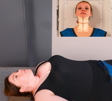
FIGURE 38.22 Cervical spine. Position for AP Axial projection. From Lampignano J, Ehrlich RA: Bontrager’s textbook of radiographic positioning and related anatomy, ed 10, St. Louis, 2021, Mosby.
• Patient instructions: Do not breathe during the exposure.
• Structures seen: Vertebrae C3-T2, including bodies, articular pillars, and intervertebral disk spaces.
AP Projection Open Mouth Technique (Upper Cervical Spine)
• Body and part position: Seated, standing, or supine. Patient faces the x-ray tube with midsagittal plane of both body and head are aligned perpendicular to center of IR. Head is adjusted so that a line between mental lower surface of upper teeth (occlusal plane) and base of skull is parallel to horizontal plane.
• CR: Perpendicular to center of IR, through midpoint of open mouth.
• Patient Instructions: Open mouth as wide as possible. Do not breathe during the exposure.
• Structures seen: Lateral masses and transverse processes of atlas, dens, and upper half of body of axis, seen between upper and lower teeth.
Lateral Projection (Grandy Method)
• SID: 60 to 72 inches is recommended due to the increased OID
• Body and part position: Seated or standing. Midsagittal planes of body and head are parallel to IR with infraorbital line parallel to floor. Shoulders must be relaxed and depressed. IR is positioned so that the upper margin is about 1 inch above the external auditory meatus (EAM).
• CR: Perpendicular to center of IR through body of C4.
• Patient instructions: Do not breathe during the exposure.
• Structures seen: All seven cervical vertebrae and soft tissues of anterior neck, including spinal alignment, bodies, disk spaces, spinous processes, and zygapophyseal joints.
If the patient is unable to perform the routine projections for the cervical spine due to trauma, supplemental projections may be performed. Supplemental projections utilize modified positioning to obtain the needed projections.
Lateral Projection in Flexion and Extension
Lateral projections with cervical spine in flexion and extension are performed to evaluate intersegmental stability.
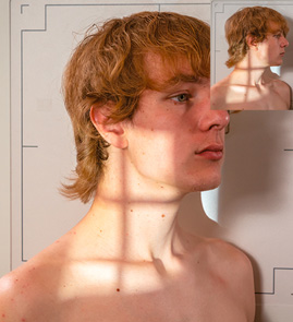
FIGURE 38.23 Cervical spine. Position for AP oblique projection. From Lampignano J, Ehrlich RA: Bontrager’s textbook of radiographic positioning and related anatomy, ed 10, St. Louis, 2021, Mosby.
• IR: CR plate 24 × 30 cm, portrait orientation.
• SID: 60 to 72 inches is recommended due to the increased OID.
• Body and part position:
• Position for flexion: Patient is positioned as for routine lateral projection. Patient is then instructed to tuck chin close to neck and then to flex neck, attempting to look at a spot midsternum.
• Position for extension: Patient is positioned as for routine lateral projection. Patient is then instructed to extend neck, looking at a spot on ceiling directly above head.
• CR: Perpendicular to center of IR through body of C4.
• Structures seen: All seven cervical vertebrae and soft tissues of anterior neck, including spinal alignment, bodies, disk spaces, spinous processes, and zygapophyseal joints. Head tilted face down in flexion and tilted face up in extension.
Oblique Projections
Bilateral oblique projections are taken. Patient may be positioned PA (right and left anterior oblique) or AP (right and left posterior oblique). They may be done recumbent, with a 40-inch SID, or upright, with either a 40-inch or 72-inch SID.
• SID: SID 60 to 72 inches is recommended due to the increased OID.
• Body and part position: Seated, standing, or recumbent. Coronal plane of the body forms an angle of 45 degrees with plane of IR. Sagittal plane of skull is perpendicular to coronal plane of body. Have patient elevate and, if necessary, protrude the chin so that the mandible does not overlap the spine (FIGURE 38.23).
• CR:
• AP obliques: Angled 15 degrees cephalad to center of IR through body of C4.
• PA obliques: Angled 15 degrees caudad to center of IR through body of C4.
• Structures seen: AP obliques demonstrate intervertebral foramina on side farthest from IR. PA obliques demonstrate intervertebral foramina on side nearest IR.
Lateral Projection of Cervicothoracic Region
The lateral projection of the cervicothoracic region is commonly called the swimmer’s lateral projection. It is used when routine lateral projections of either the cervical or the thoracic spine fail to demonstrate this area adequately. The shoulder positions create a small window between the shoulders, and the cervicothoracic spine is projected into this relatively open area.
• IR: CR plate 24 × 30 cm, portrait orientation.
• Body and part position: Seated, standing, or recumbent. Sagittal planes of body and head are parallel to IR. Arm nearest IR is raised above the head, and shoulder is rounded anteriorly. Opposite shoulder is depressed and slightly posterior.
• CR: Perpendicular to IR at C7-T1 interspace. CR enters at level of C7 spinous process.
• Structures seen: Vertebrae C6-T3 (C5-T5 with larger IR) in lateral projection without significant rotation. Bodies, disk spaces, spinous processes, and zygapophyseal joints are demonstrated between shoulders.
Positioning and Radiographic Examination of the Thoracic Spine
Learning Objective: Explain the positioning and radiographic examinations for the thoracic spine.
There is significant variation in tissue density between the extreme ends of the thoracic spine. Near the neck, there is much less tissue to penetrate than at the level of T12 in the upper abdominal region. Therefore, the anode heel effect should be utilized. For recumbent studies, the patient should be instructed to lie on the table with the head toward the anode end of the x-ray tube.
In the lateral projection, the density variation is reversed. The proximal thoracic spine is more difficult to penetrate due to the bone and muscle mass of the shoulders. The inferior portion is easily penetrated because its mass is largely air-containing lung. The first three thoracic vertebrae are rarely seen well on the lateral projection. When the upper thoracic vertebrae are the area of clinical interest, it is customary to include the swimmer’s lateral projection of the cervicothoracic region.
For this examination, the patient should undress down to the waist and don a gown that opens in the back. This will facilitate visualization and palpation of the spine. Jewelry should be removed.
The routine examination of the thoracic spine includes the AP and lateral projections.
• IR: CR plate 35 × 43 cm, portrait orientation.
• Body and part position: Seated, standing, or supine. Midsagittal plane of body is perpendicular to IR and centered on it, with patient facing the x-ray. Superior border is aligned 1.5 to 2 inches above the shoulders. When patient is supine, it is helpful to bolster the knees. When patient is standing, feet should be shoulder width apart and patient’s back should be firmly against IR holder.
• CR: Perpendicular to center IR at T7. This point is midline at the approximate midpoint of sternum.
• Patient instructions: Suspend breathing on expiration.
• Structures seen: All 12 thoracic vertebrae, particularly the bodies, disk spaces, and transverse processes. C7 and at least a portion of L1 are usually also seen.
Lateral Projection
• IR: CR plate 35 × 43 cm, portrait orientation.
• Body and part position: Seated, standing, or supine. Sagittal plane of body is parallel to IR. Center the posterior half of the thorax to the midline of the IR. Arms should be elevated overhead or anterior to the body with shoulders rounded anteriorly. The superior border of the IR is aligned 1.5 to 2 inches above the shoulders. The entire length of thoracic spine should be parallel to IR. When patient is recumbent, it is helpful to support the knees with a sponge under the waist (FIGURE 38.24).
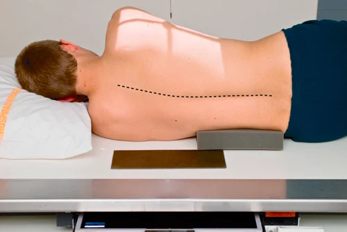
FIGURE 38.24 Thoracic spine. Position for lateral projection. From Lampignano J, Ehrlich RA: Bontrager’s textbook of radiographic positioning and related anatomy, ed 10, St. Louis, 2021, Mosby.
• CR: Perpendicular to center IR at T7. CR enters at inferior angle of scapula through middle of posterior half of thorax.
• Patient instructions: Perform shallow breathing during exposure.
• Structures seen: T3 through T12 with blurring of ribs and lung markings when breathing technique is used.
Positioning and Radiographic Examination of the Lumbar Spine
Learning Objective: Explain the positioning and radiographic examinations for the lumbar spine.
Patients should remove outer clothing from the torso for lumbar spine imaging and don a gown opening in the back. Female patients must remove under garments.
Routine Examination of the Lumbar Spine
The routine examination of the lumbar spine includes AP or PA and lateral projections.
AP and PA Projection
• IR: CR plate 35 × 43 cm, portrait orientation.
• Body and part position: Standing or supine.
• AP: Patient faces the x-ray with midsagittal plane of body perpendicular to IR and centered on it. When patient is supine, knees are flexed and may be supported with a bolster. When patient is standing, feet should be shoulder-width apart and patient’s back should be firmly against IR holder.
• PA: Patient stands facing IR or lies prone, with midsagittal plane perpendicular to IR and centered to it.
• CR: Perpendicular to center IR at L4 and midline at the level of iliac crest.
• Patient instructions: Suspend breathing on expiration.
• Structures seen: All five lumbar vertebrae, intervertebral disk spaces, proximal portion of the sacrum, and sacroiliac SI joints. This projection demonstrates the bodies, disk spaces, and transverse processes. The pedicles are seen on end.
Lateral Projection
• IR, CR, and patient instructions: Same as the AP projection.
• Body and part position: Standing or supine.
• Supine: Spine is parallel to center of Bucky with arms anterior to body. Radiolucent sponges may be used to elevate waist to align the spine. Knees are flexed. A pad between knees helps keep pelvis lateral and maintains lateral position of the spine (FIGURE 38.25).
• Upright: Feet are shoulder-width apart, and torso is stabilized against upright IR. Arms are crossed over chest with hands supported on shoulders.
• Structures seen: All five lumbar vertebrae and superior half of sacrum, including intervertebral foramina, spinous processes and profile of the bodies, and intervertebral disk spaces.
Supplemental Projections of the Lumbar Spine
If the patient is unable to perform the routine projections of the lumbar spine due to trauma, supplemental projections may be performed. Supplemental projections utilize modified positioning to obtain the needed projections.
AP Oblique Projection
Bilateral oblique projections are taken. AP obliques (right posterior oblique [RPO] and left posterior oblique [LPO] positions), rather than PA obliques, are most common because they demonstrate the pars interarticularis and the zygopophyseal joints of the side nearest the IR, providing better detail.
• IR: CR plate 35 × 43 cm, portrait orientation.
• Body and part position: Standing or supine. Sagittal plane is aligned 45 degrees to IR.
• Supine: From supine position, patient is rotated 45 degrees toward the side being imaged. Position may be supported by a large 45-degree radiolucent sponge. The entire spine is rotated the same amount so there is no torsion (twist) of the spine (FIGURE 38.26A).
• Upright: From AP position, patient is rotated 45 degrees toward the side being imaged. Feet are shoulder-width apart, and torso is stabilized against upright IR.
• CR: Perpendicular to center IR at L3. CR enters a point 2 inches medial to ASIS farthest from IR and 1.5 inches superior to iliac crest.
• Patient instructions: Suspend breathing on expiration.
• Structures seen: All five lumbar vertebrae and upper portion of the sacrum, including zygapophyseal joints and pars interarticularis on side nearest the IR.
Lateral Projection of L5-S1 Lumbosacral Junction
If there is poor visualization of the lumbosacral junction in the routine lateral projection, a collimated image of the area is recommended. This projection is important because this junction is a common site of chronic low back pain. Although this projection may be taken with the patient upright, the recumbent position produces superior results.
• Body and part position: Same as routine lateral lumbar projection, with care taken that spine is parallel to IR (FIGURE 38.26B).
• CR: Perpendicular to center IR through lumbosacral junction. This centering point is 2 inches posterior to ASIS and 1.5 inches inferior to iliac crest on coronal line midway between ASIS and posterior prominence of sacrum. When spine cannot be aligned, angle 5 degrees for males and 8 degrees for females.

FIGURE 38.25 Lumbar spine. (A) Position for lateral projection. (B) Lateral projection. A, from Lampignano J, Ehrlich RA: Bontrager’s textbook of radiographic positioning and related anatomy, ed 10, St. Louis, 2021, Mosby. B, from Long BW, Frank ED, Ehrlich RA: radiography essentials for limited practice, ed 6, St. Louis, 2021, Elsevier.
• Patient instructions: Suspend breathing on expiration.
• Structures seen: The lower one or two lumbar vertebrae, the upper sacrum, and an open lumbosacral junction.
Positioning and Radiographic Examination of the Lumbar Spine and Sacroiliac Joints
Learning Objective: Describe the positioning and radiographic examinations for the lumbar spine and the sacroiliac (SI) joints.
The examinations of the lumbar spine and sacroiliac (SI) joints are most commonly performed in the table Bucky.
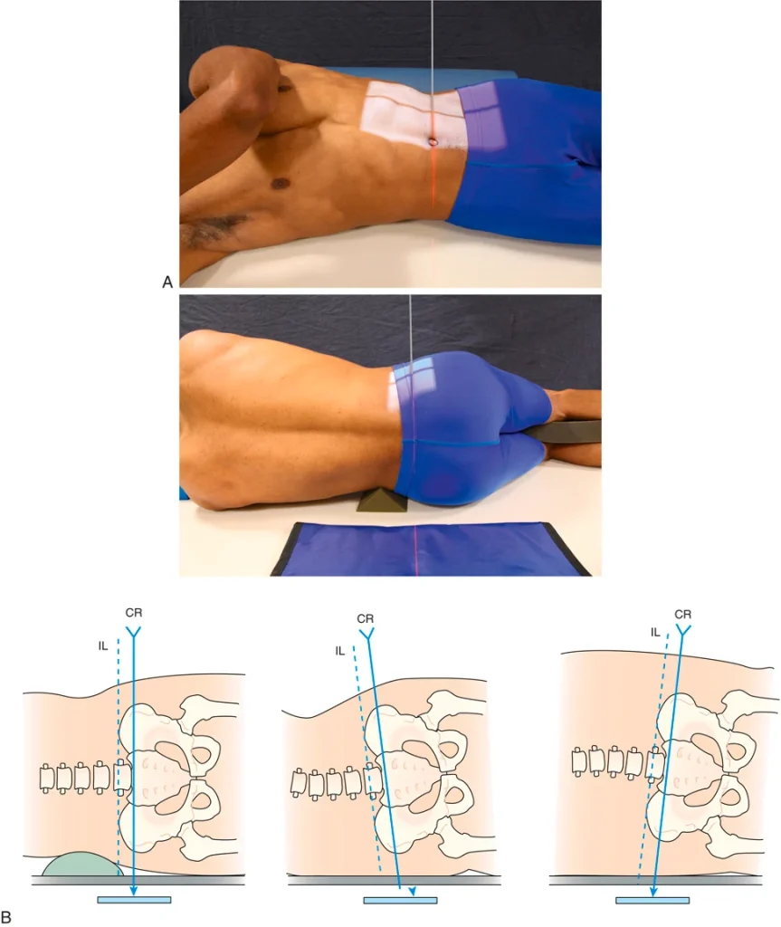
FIGURE 38.26 Lumbar spine. (A) Position for AP oblique (RPO) projection. (B) Position for lateral projection of L5-S1 lumbosacral junction. A, from Long BW, Rollins JH, Smith BJ: Merrill’s atlas of radiographic positioning and procedures, ed 14, St. Louis, 2020, Mosby. B, in Long BW, Rollins JH, Smith BJ: Merrill’s atlas of radiographic positioning and procedures, ed 14, St. Louis, 2020, Mosby; modified from Francis C: Method improves consistency in L5–S1 joint space films, Radiol Technol 63:302, 1992.
AP Axial Projection of Lumbosacral Junction and Sacroiliac Joints
Because of the sacral base angle, the lumbosacral junction is not well seen on the routine AP projection of the lumbar spine. The AP axial projection directs the CR parallel to the sacral base. This projection is also useful for demonstration of the SI joints.
• Body position: Supine, same as routine recumbent lumbar spine, with knees flexed and supported.
• CR: Angled 30 degrees cephalad for males and 35 degrees for females. CR is directed to center of IR through lumbosacral junction. CR enters in midline, 1 inch inferior to the ASIS.
• Structures seen: Open lumbosacral junction, sacral alae, and SI joints.
Sacroiliac Joints
The routine examination of the SI joints includes the AP oblique projections. The AP axial projection of the lumbosacral junction and the SI joints may also be included.
• Body and part position: Recumbent.
• AP obliques (RPO, LPO positions): From supine position, body is rotated so that the coronal plane is aligned at an angle of 25 to 30 degrees to IR. The side of interest is elevated, farthest from IR. Position may be supported by a radiolucent sponge under hip and lumbar area of elevated side. The entire spine is rotated the same amount so that there is no torsion of the spine.
• PA obliques (RPO, LPO positions): From prone position, body is rotated so that the coronal plane is aligned at an angle of 25 to 30 degrees to IR. The side of interest is nearest the IR. Position may be supported by a radiolucent sponge under hip on opposite side. The entire spine is rotated the same amount so that there is no torsion of the spine.
• CR:
• AP obliques: Perpendicular to center of IR through point 1 inch medial to ASIS farthest from IR.
• PA obliques: Perpendicular to center of IR through point 1 inch medial to ASIS nearest the IR.
• Patient instructions: Suspend breathing on expiration.
• Structures seen:
• AP obliques: SI joint farthest from IR.
• PA obliques: SI joint nearest IR.
Positioning and Radiographic Examination of the Sacrum
Learning Objective: Explain the positioning and radiographic examinations for the sacrum.
The routine examination of the sacrum includes the AP axial and lateral projections. Patient should be instructed to stop breathing during the exposure.
AP Axial Projection
• IR: CR plate 24 × 30 cm, portrait orientation.
• Body and part position: Supine or recumbent. Midsagittal plane is perpendicular to IR and centered to it. Knees are flexed and supported with a bolster, if needed (FIGURE 38.27).
• CR: Angled 15 degrees cephalad to enter body at midline, 1 inch inferior to the ASIS.
• Structures seen: Entire sacrum and SI joints.
Lateral Projection
• IR: Same as the AP axial projection.
• Body and part position: Recumbent. Sagittal plane is parallel to IR. Spine is aligned parallel to center of Bucky with arms anterior to body. Radiolucent sponges may be used to elevate waist or hips to align the spine. Knees are flexed. A pad between knees helps maintain lateral positions of pelvis and spine.
• CR: Perpendicular to center of IR through center of sacrum. CR enters a point 3.5 inches posterior to ASIS.
• Structures seen: Entire sacrum and lumbosacral junction. Coccyx is sometimes seen.
Positioning and Radiographic Examination of the Coccyx
Learning Objective: Explain the positioning and radiographic examinations for the coccyx.
AP Axial Projection
• Body and part position: Recumbent. Coronal plane is parallel to IR with patient facing the x-ray tube. Midsagittal pane is centered to midline of Bucky. Knees are flexed and supported with a bolster, if needed.
• CR: Angled 10 degrees caudad to enter body at midline, 1 inch inferior to the ASIS.
• Structures seen: Entire coccyx and distal portion of sacrum.
Lateral Projection
• Body and part position: Recumbent. Sagittal plane is parallel to IR. Knees are flexed and may be supported by a sponge.
• CR: Perpendicular to center of IR through center of coccyx. CR enters a point 2 inches inferior to ASIS.
• Patient instruction: Stop breathing during the exposure.
• Structures seen: Entire coccyx and distal portion of sacrum.
Positioning and Radiographic Examination of the Full Spine
Learning Objective: Explain the positioning and radiographic examinations for the entire spine.
It is sometimes desirable to demonstrate the entire spine in one image. This is useful for the evaluation of scoliosis. Some chiropractic physicians also use it for the evaluation of the entire spine with the patient weight bearing. The routine examination of the full spine includes the PA only, however, lateral projections may be performed for abnormal spinal curvatures.
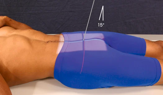
FIGURE 38.27 Sacrum. Position for AP axial projection. From Long BW, Rollins JH, Smith BJ: Merrill’s atlas of radiographic positioning and procedures, ed 14, St. Louis, 2020, Mosby.
PA Projection
• IR: CR plate 14 × 36 cm, portrait orientation.
• SID: SID 60 inches minimum
• Body position: Standing. Height of grid and IR is adjusted to include area from top of patient’s ears to level of greater trochanters. Head is positioned as for AP axial projection of upper cervical spine, with neck extended slightly to allow for angulation of diverging x-ray beam at upper extreme of exposure field.
• CR: Perpendicular to center of IR, entering at midline approximately at level of xiphoid process.
• Patient instructions: Stop breathing during the exposure.
• Structures seen: Portion of mandible, entire spine, portion of pelvis.
Lateral Projection
• IR, SID, CR, and patient instructions: Same as with full spine.
• Body position: Same as for upright lateral projection of thoracic spine. Shoulders are rounded anteriorly, and arms are extended anterior to body and supported
• Structures seen: Portion of mandible and skull, entire spine, portion of pelvis.
Pathology
Learning Objective: Describe the pathology found in an examination of the spine.
Radiographic examination of the spine is critical for evaluating pathology.
Congenital Abnormalities
The spine is a common site for congenital abnormalities and deformities. A transitional vertebra occurs when a vertebra of one region takes on features of the adjacent region. Sacralization of L5 occurs when one or both spinous processes of L5 become fused to the sacrum. When the first sacral segment fails to fuse with the remainder of the sacrum, this is known as lumbarization.
Another congenital deformity of the spine is spina bifida, which results when the posterior portions of the neural arches fail to close during the embryo’s development.
Spinal Fractures
Spinal fractures typically are the result of trauma. Fractures of vertebral bodies are often compression fractures with anterior wedging. Pathologic fractures are fractures that occur with little or no trauma, the bones are weakened by disease processes. Pathologic compression fractures of the thoracic spine caused by osteoporosis are often seen in older women.
Spondylosis, Spondylitis, Spondylolysis, Spondylolisthesis, and Spondyloschisis
All of these refer to different conditions, but the words look and sound very much alike. They all have the same root, spondylo-, which simply means “vertebra.”
• Spondylosis: Fixation or fusion of vertebrae.
• Spondylitis: Often applies specifically to tuberculosis disease of the vertebrae, which is also called Potts disease. Spondylitis is also seen with rheumatoid arthritis.
• Spondylolysis: The breakdown of the structure of the bone, which occurs with osteoporosis, with some metastatic lesions, and other conditions that cause atrophy and bony destruction.
• Spondylolisthesis: Anterior displacement of one vertebra on another. It occurs most often at the lumbosacral joint and is usually caused by a defect or a fracture of the pars interarticularis or the pedicle.
• Spondyloschisis: A congenital fissure (split or cleft) in the neural arch (e.g., spina bifida occulta).
Disk Pathology
The pulpy center of intervertebral disks is normally a gel-like, semiliquid material. With the pressure of spinal movement, Its mass shifts to change the shape of the disk. With advancing age and repeated minor trauma to the spine, the disks tend to degenerate. The nucleus may dry out and become atrophied, which causes narrowing of the disk space. Without adequate cushioning, the joint becomes inflamed, and the surrounding bony structures show signs of degeneration. This condition is known as degenerative disk disease (DDD) and is usually associated with osteoarthritis.
Disk herniation or herniated nucleus pulposus (HNP) is the condition often called “slipped disk.” The annulus fibrosus ruptures, and the nucleus is forced into the area posterior to the disk space.